PeX Progress Update 2
Published at May 7, 2024
We are designing and building a physical game console for the PICO-8 - a charming platform for building retro games. Previously, I built a breadboard prototype of the console, designed and ordered the circuit boards, and then ran some tests.
Today, we will be iterating on the design of the circuit boards as well as creating an enclosure for the console.
You can join us on the development journey by sliding into our discord. You can also support us by wait-listing.
Without a working main board, it was quite difficult to run any meaningful tests, so I focused on completing the second iteration of the board with all the planned improvements - notably changes to the component footprints to make soldering easier, and exposing test points to take electrical measurements. Alongside the next-gen board, it was also time to begin prototyping the enclosure and thinking about the console’s form factor.
Enclosure Design
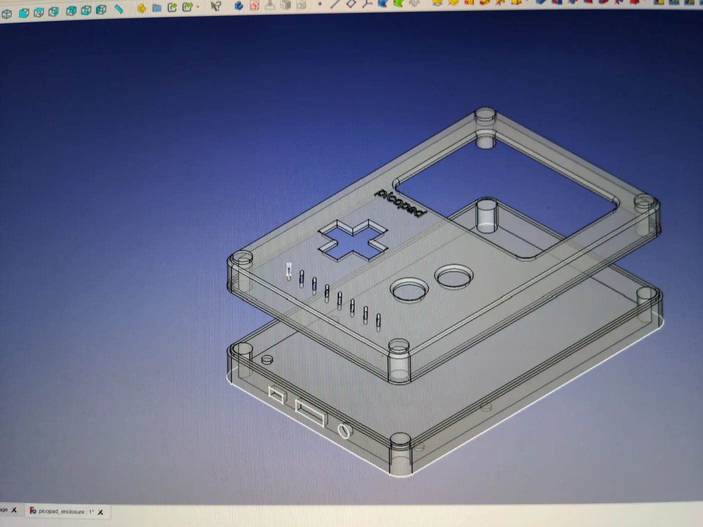
My initial choice for CAD software was an open source option called FreeCAD. Over a weekend, I whipped up the first version of the enclosure, which was loosely modeled after the Game Boy. I will definitely iterate and improve on this design as I get better at modeling and industrial design.
After completing this first version, I decided that the FreeCAD was too frustrating to continue with. My biggest gripe with this tool was that the error reporting was not very user friendly, so the design would completely break often and you had to track down the issue.
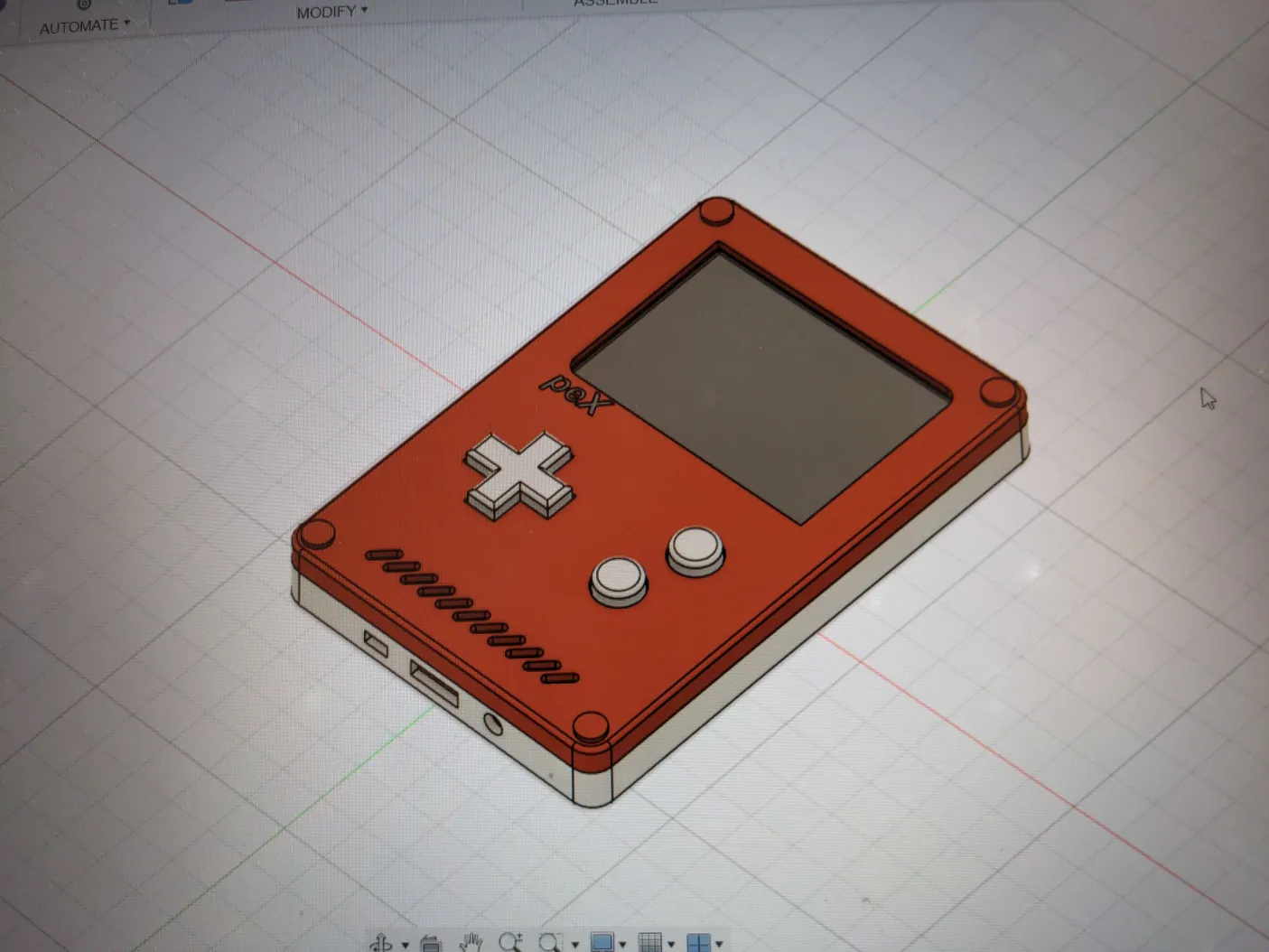
After investigating some alternative options, I settled on Fusion 360, which seemed to be quite popular and had a sleek user interface. In a fraction of the time, I was able to reproduce my design. While I would like to continue using open-source tools, Fusion is just too convenient to pass up. I did hear about Ondsel, a project that builds on and improves FreeCAD, so I might give it a shot in the future. OpenSCAD is also an option, where you use code to create models. However, it seems too gimmicky for production work at first glance.
PCB Design
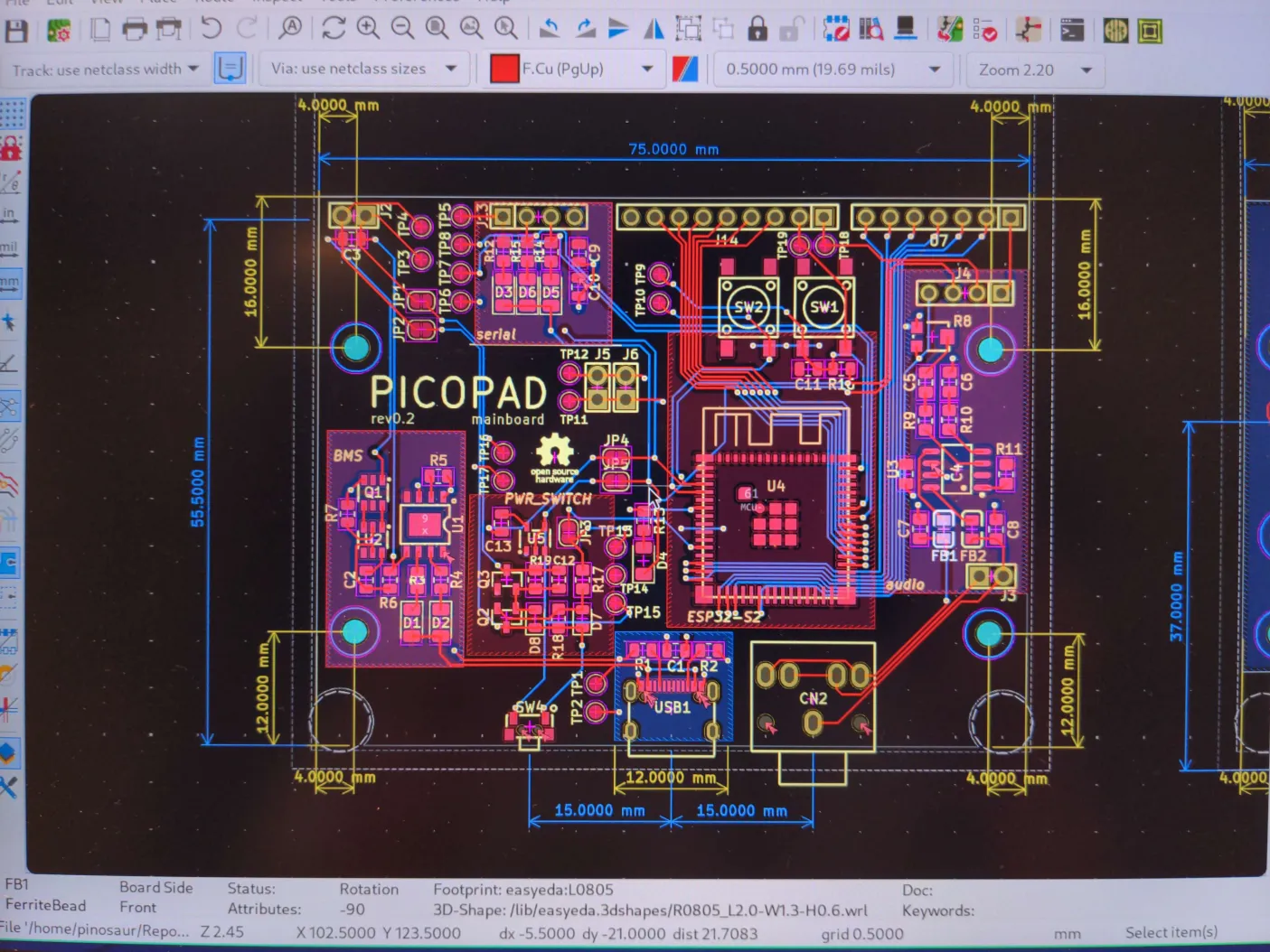
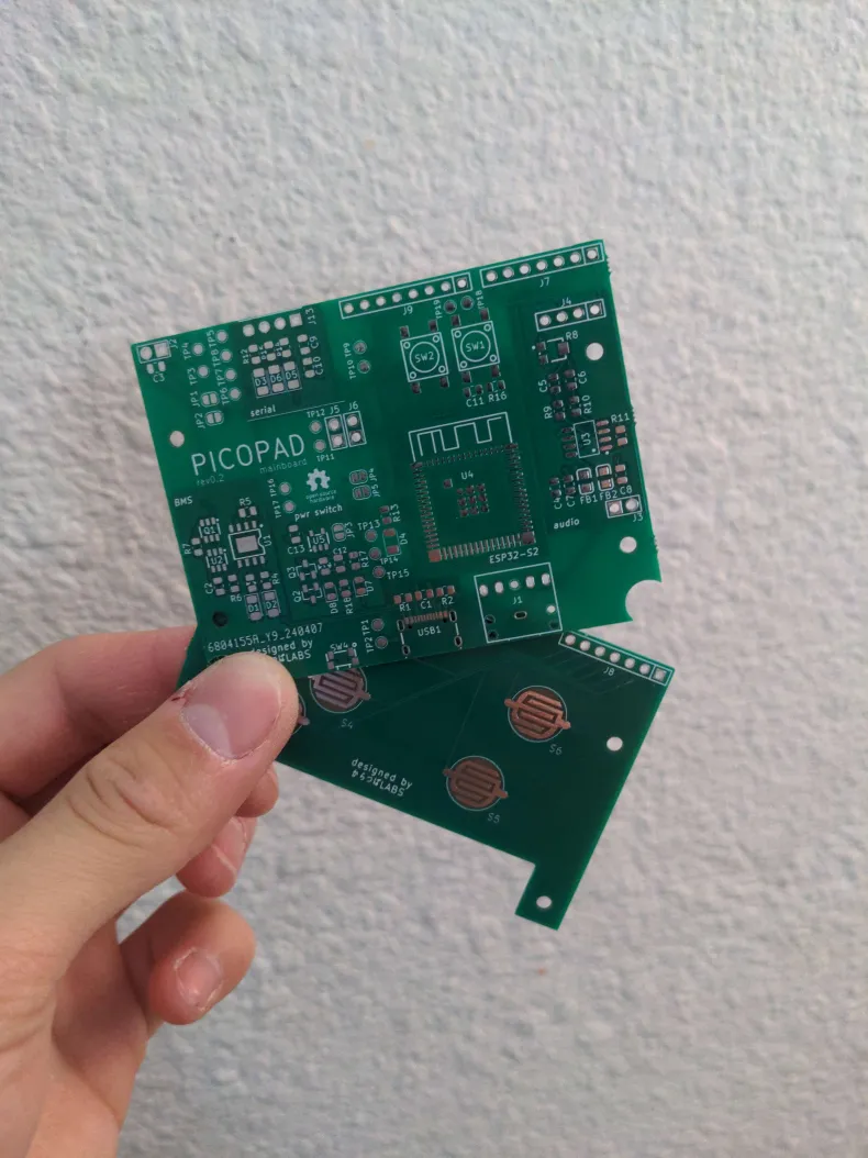
The idea is to mount the main board, which includes the ESP32 microcontroller and supporting circuits, to the bottom part of the enclosure. A spacer will then be used to mount the game pad at the right height so it aligns perfectly with the holes for the buttons on the top part. Since I was already confident in the battery, audio, and game pad boards, I combined everything onto one board and dimensioned it to fit snugly within the planned enclosure. I also found a cool power button circuit that lets you turn on the console with a press and turn it off by holding the power button for a set amount of time.
I learned a lot about PCB design since the previous version, which is reflected in the new design. It features many test points, solder bridges to isolate modules for incremental testing, and component references to make placing components easier. The KiCAD autorouter (which automatically places the circuit lines) was a bit funky, so I hand-routed all the traces over a few hours. It’s a giant tangle of copper traces, but it looks like it’s coming together quite well!
After about a week, the new boards were at my door!
Soldering and Assembly
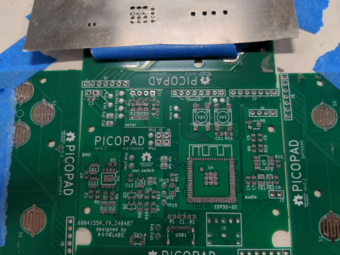
I also invested in getting a solder stencil, which is a sheet of metal with holes that align with where you need solder applied. This made the assembly process an absolute breeze, especially for the tiny components. I still had a bit of trouble getting an even coat, but despite this, the reflow soldering went perfectly! Placing all the components was also a tedious and manual process, so hopefully we can get enough funding to justify buying a LumenPNP - an open-source pick-and-place machine that I have been eyeing for some time :)
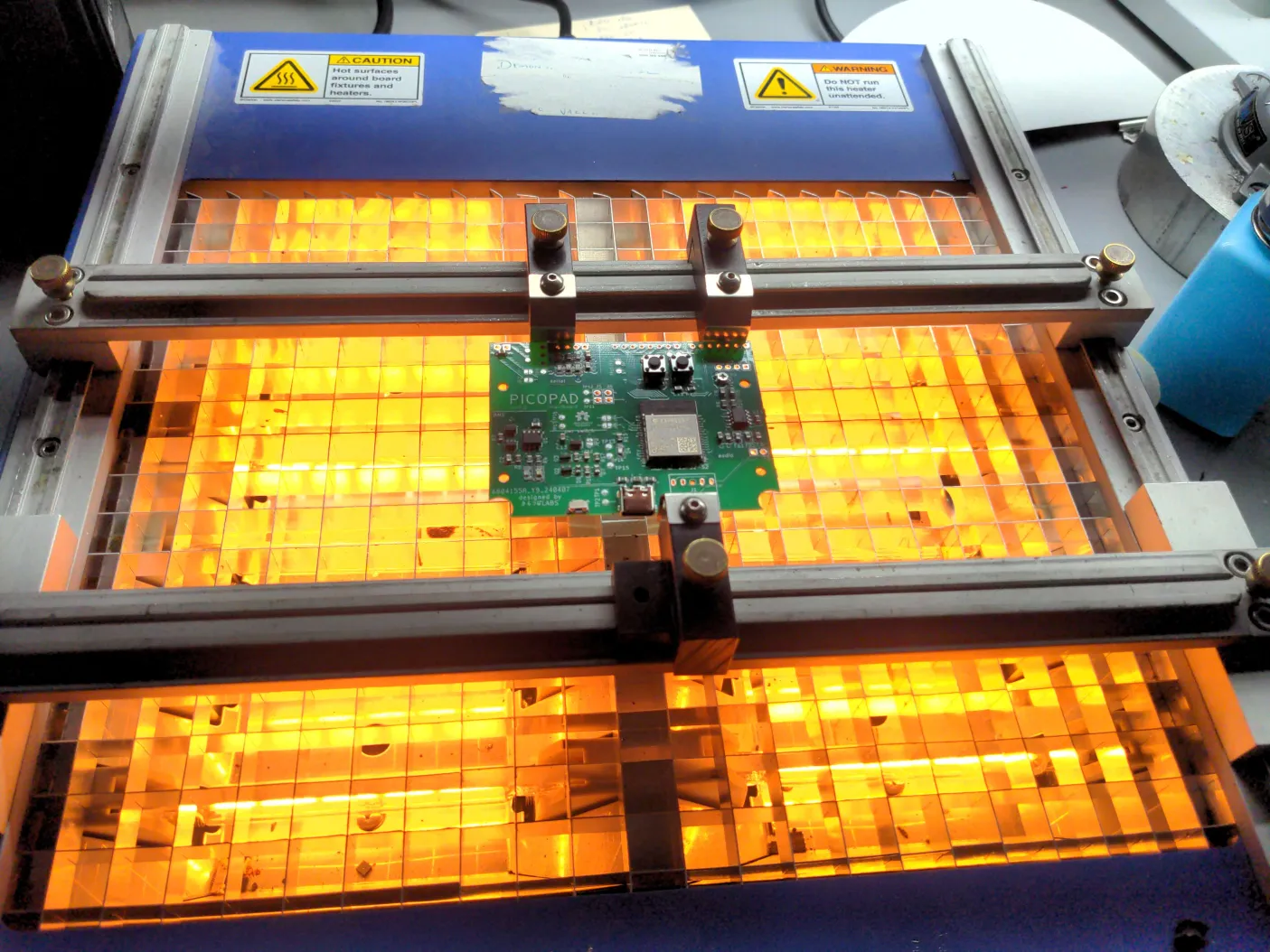
My first attempt at reflow soldering was with a hot air gun. Since this revision of the board had much larger pads, I was able to heat up the board long enough until I could visually confirm that the soldering process was complete.
Although the soldering itself went flawlessly, I misaligned the ESP32 on the pads, which ended up shorting power and ground. Rather than removing the ESP32 using a hot air gun, one of my coworkers had recently built a Controleo3— a toaster oven that is modded into a reflow oven (WHAT?), so I was eager to try it out. After applying paste and placing components on a new board, it was time to test it out!
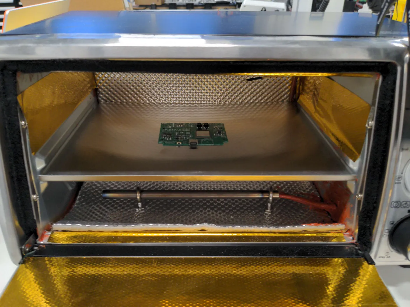
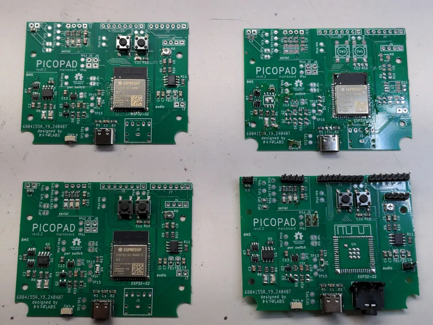
The soldering quality was similar to using the hot air gun, but it was much less manual, and I was more confident I didn’t accidentally burn a component. If I have some spare time, I definitely want to build one of my own. Here’s a bunch of the successful (and failed) board attempts at the end.
Testing
With the boards assembled, it was time to test programming one of these boards! This should definitely work, right? Right?
Nope.
It seems there’s something wacky going on when using the serial programmer. The TX/RX indication lights on the mainboard side are not seeing any traffic, while the indicator lights on the serial programmer are. Strange.
After an embarrassingly long time debugging, I realized I had forgotten to change the build target from ESP32 to ESP32-S2, since the original dev board was an ESP32.
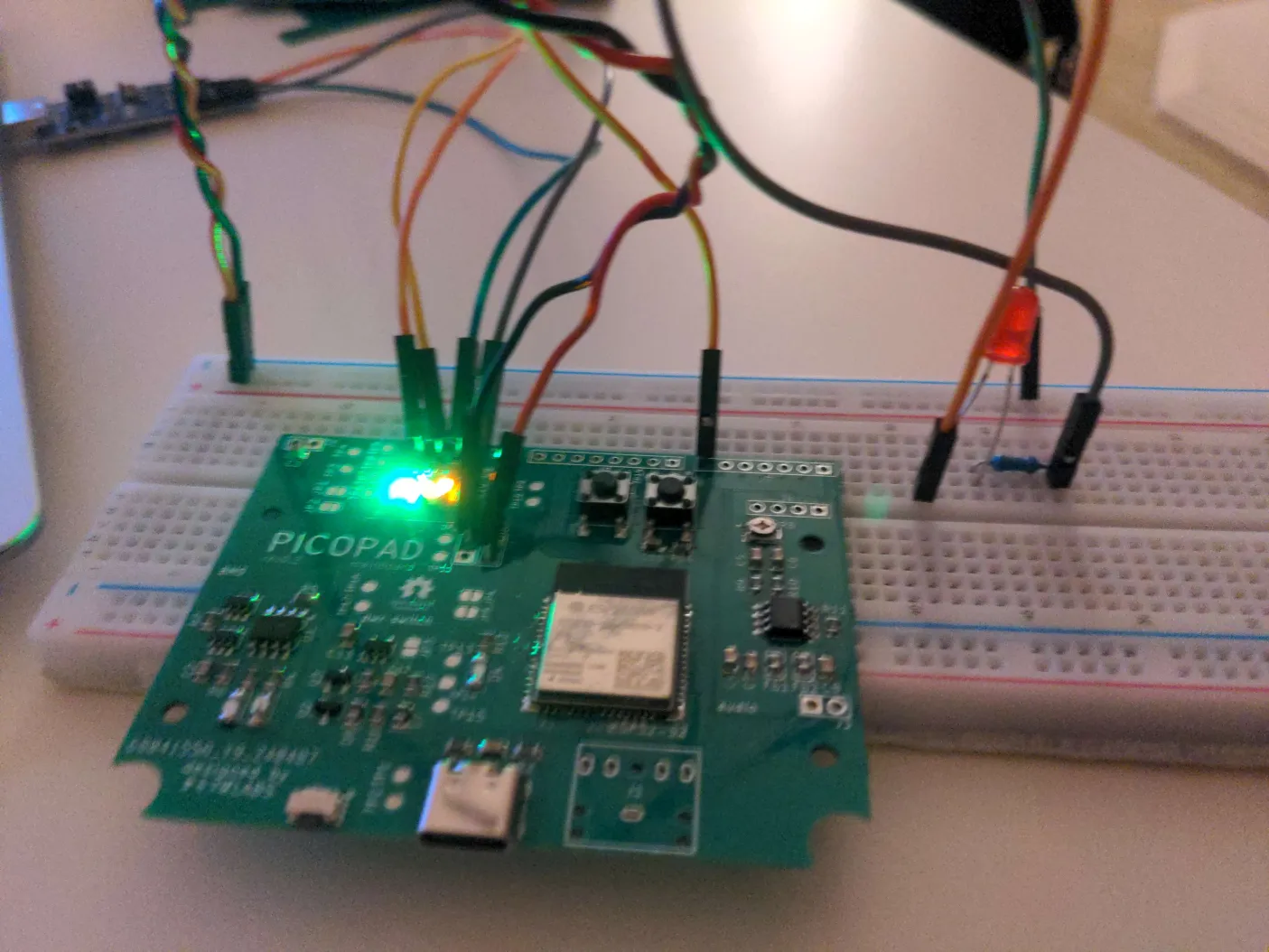
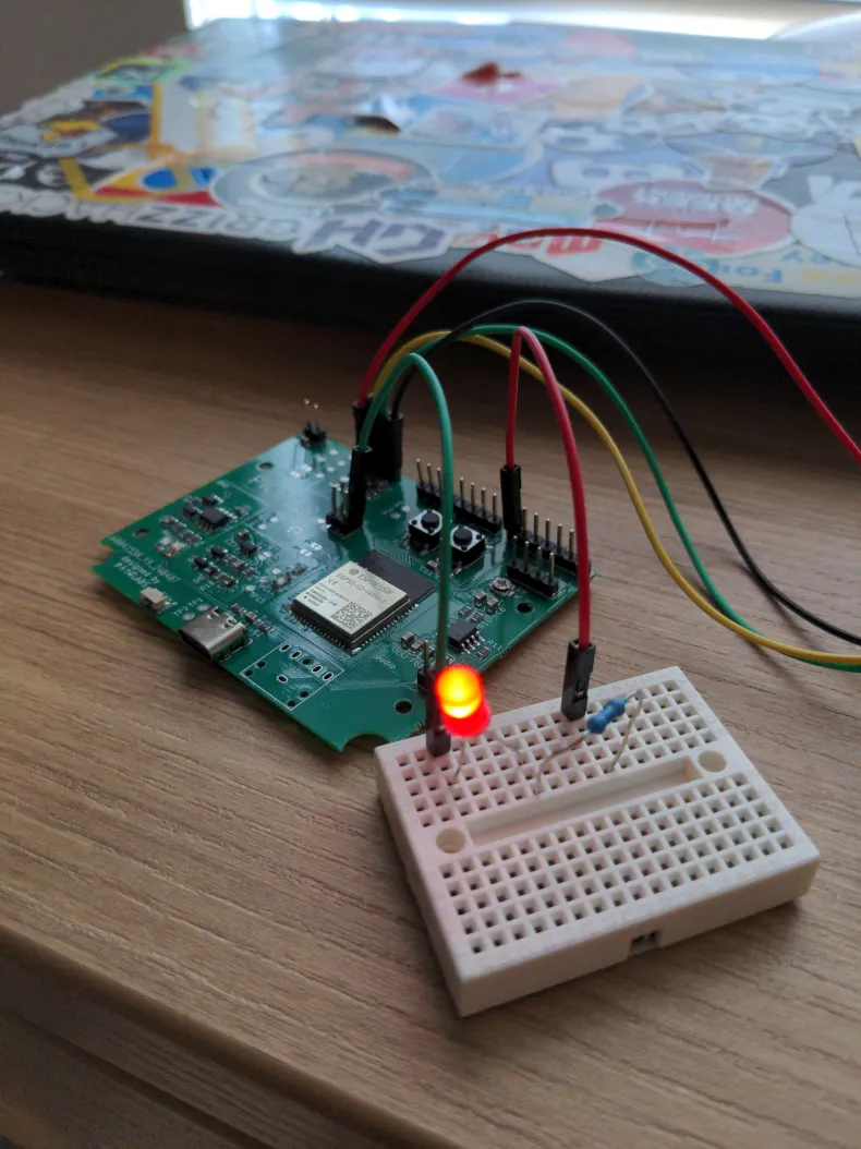
With that, the first successful code upload was done on the board. Here’s the board running a simple “blinky program” that pulses an LED on and off! I’ve never been quite this happy to see an LED turn on.
3D printing
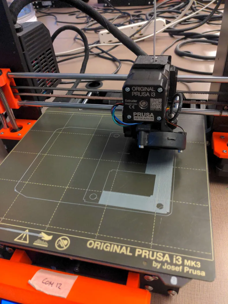
Following this, it was time to 3D print the enclosure. Previously, I had been traveling a lot and couldn’t find a reliable place to 3D print. Now that I am back in school, we have dedicated facilities with 3D printers, so I can print to my heart’s content!
And here it is completed!
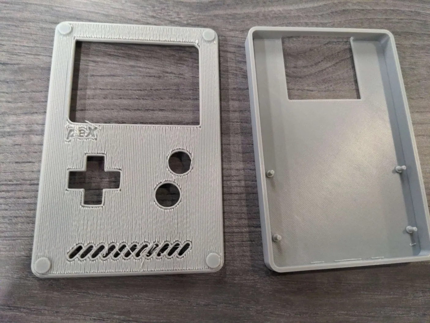
Since I printed the top enclosure piece face down, removing the skirt and supports left a horrible rough texture. I will experiment with more print settings and orientations to improve this.
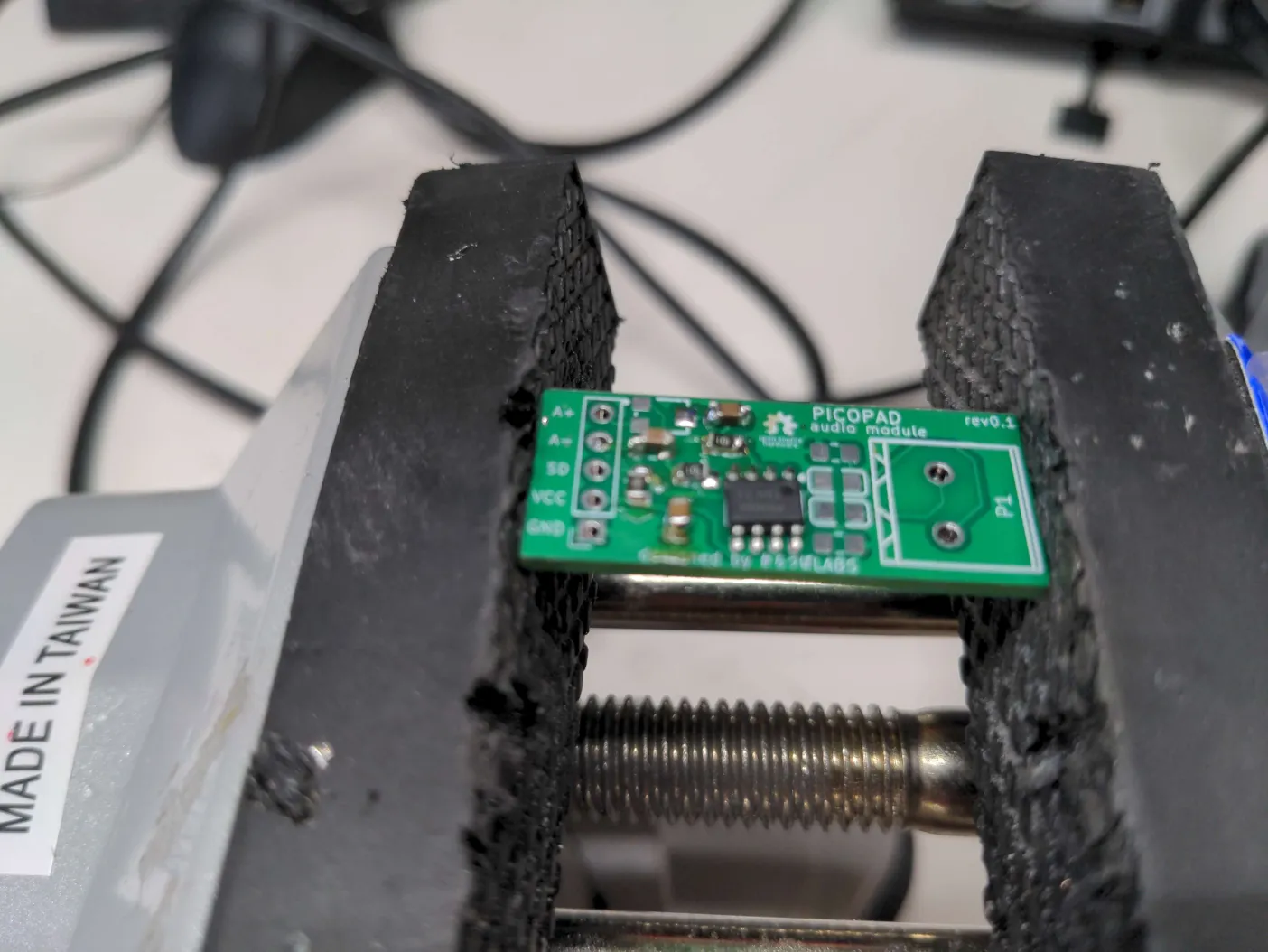
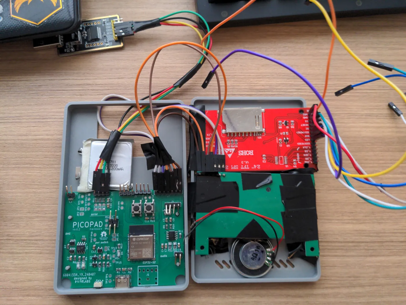
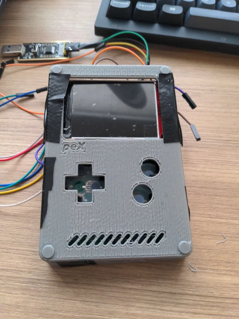
I then tried fitting all the components into the enclosure, which ended up quite snug. Although I hadn’t accounted for the height of the debug pin headers, so I bent them all with a clamp. Somehow, I also completely mismeasured the button pad size, so the gamepad is horribly misaligned. Nothing a reprint couldn’t solve though.
And that’s a wrap for this progress update! Next, we will be iterating on the enclosure design and exploring a cartridge system. See you soon!
- pinosaur